Optimize and Evaluate Using Blitzortung Data
Working Draft OCTOBER 2019 DEVELOPMENT V4b
FULL SCREEN is BESTUSING THE BLITZORTUNG.ORG DATA STRICTLY, NOT LightningMaps.org. Blitzortung.Org is the primary website. (LMO may be using some experimental algorithms at times, there may be some other issues notably (Oct 2019) Asia / Japan assigned stations may not be shown individually on LightningMaps, no 'finalized' updates have been made to LMO, ... this should be obvious, especially as LMO allows a visitor to select map data from LMO ot Blitzortung, or Both..Statistics generated on Station pages on LMO may reflect only LMO data calculations.
I look at ratios derived from the Station List Page... and the newer Region Relative graphics displayed on the Operator's page.
Optimization is NOT a fast, one-time look and tweak... it cannot be done reliably in 'automatic', it must be evaluated over time, seasons, etc. Also I am NOT in competition with any other station. My stations and configurations don't live where they live. Cell vectors and distance, ionosphere properties, magnetic field lines, geology, local EM environment are all different...Optimization is for my specific situation, no one else.
Biggest secret: LOCATION LOCATION LOCATION - of H field antennas, and E probe. I cannot optimize with antennas in my computer room. H fields can work in any quiet electrical environment, even in a basement, attic, etc... The E probe assembly MUST be outside for optimum performance, not grounded, at least a couple of meters in the air on a non-metal pole, isolated - away from noise sources, structures, etc. Find your sweet spot! What's good for E may not be good for H... vice versa... they are totally different reception principles... see Propagation.
I use the Controller interface 'signals' to optimize, over time, my settings for the controller. This MUST be weighed against what the Server decides about ‘my optimized signals’. To Evaluate, I now use Blitzortung: Total, Valid, Involved, Used. Once my average EM environment is established, that gives me my base line. I remain in full manual, and may or may not go back and change a gain setting on a channel in extreme situations related to expected or active interferers...which force interference mode or excessive junk signals. Once set, if cell location and activity, or interferers, force interference mode, I generally let it ride., That's the way it is designed to work. Nearby Cells have so much field activity that the data may be worthless for location accuracy from my stations. Those interference watchdogs are there for a reason.
UPDATE June 2021: There are NEW Region Relative graphics and data available on your operator's page. For an example and explanation see the blue ‘?’ icon at https://frankfortweather.us/fwxBLPublic/index.html in “quantity /ratios” segment.
My goal is to never send a useless signal, and those I do send (TOTAL) will include one "VALID" channel's data which MAY become INVOLVED. I know it is extremely unlikely that all valid / involved channels will be " USED" for "Location" computation. For those, I will be a 'detector' (INVOLVED), but NOT a 'locator' (USED). This is problematical for my EM Environment.
I found most 'optimization' issues are related to H field operation, rather than E field reception..
If the E probe assembly is properly designed, properly located, and as high above earth as feasible, about all that need be done is set thresholds to 100mv, and gains as appropriate. The E probe, for all practical purposes, is immune to any magnetic reception or interference. Electric arcs, yes, however. Adjust gain so doesn't trigger on typical local noise at 100mv, and move on, generally. It is a very sensitive channel.
H field reception efficiency is a bit trickier, as both near- and far-field magnetic and electric sources other than lightning impulses can affect my reception.
Recommend begin optimization with Trigger / Thresholds at 100mv. The ADC / controller computes a relative gain for system using a 100mv standard. If thresholds are different, extra computations required to compute and set relative gain for system.. Optimize then, using analog chain gain settings, attempt to achieve with threshold at 100mv. Generally, leave the "ignore signals below threshold" at the default 10%. I currently run 25%,,, sometimes a 'weaker' channel that normally would not send at 10% may contain better data than the 'trigger' channel.,.. but if this setting is too liberal, I will send more 'channels' and data than may be optimum. The Server will only select one channel for further examination... the best valid data of all channels sent..
I would never try to optimize using automatic mode. The controller will cycle gains up and down... and I want to establish my 'ambient' 'normal' parameters for the environment I live in. Automatic mode is often a bad choice for normal operation. I run full manual mode.
Looking at any signal received at the server...
![[Image: ValidSignal.png]](https://sferics.us/misc/ValidSignal.png) ...and how it may be analyzed
...and how it may be analyzed
The Process is similar to the below,... apologies for any errors...
TOTAL AND VALID ARE UNDER MY CONTROL, CONFIGURATION, OPTIMIZATION.
1. TOTAL = Signals received from station, reference to station 1 PPS GPS and have passed all Controller "criteria"
e.g.ADC Digital Trigger level at least twice noise level, amplitude within presets, sampling correct, etc.
2. VALID / TOTAL = 100% goal
CONTROLLER ADC SAMPLE RATE (currently) MUST BE 500 kHz or signals rejected
Algorithms compute "VALID": Time Sync Controller 1PPS with 1PPS at IBOD servers in Europe.
A. Noise level computed on first 25% signal data (250 µsec)
B. Peak Discharge impulse must be 3 times computed noise level
C. Must match station's channel "DNA" parameters... the "Sieve"
Sieve holds last 1000 signals received from the station.
Sieve updates and rewrites oldest signal data with newest signal data.
Channel timing correction, other parameters applied per sieve "average"(sic)
D. Standardized (expected) parameter response from Station's "Antenna Configuration'
E. Known Design Delays from Station Series (Green / Red / Blue) and Channels received
F. Any filter timing correction computed (optional filter settings e.g.)
G. Incidental algorithms.(Digital settings, digital corrections,TOGA,etc)
In testing / development: "Noise signal elimination"
H. A single BEST Channel selected. All failing any above rejected.
BEST Channel data deemed VALID.
All others rejected
INVOLVED AND USED ARE VARIABLE RELATED TO CELL LOCATIONS, ETC. USED IS THE MOST VARIABLE
INVOLVED AND USED ARE NETWORK / ENVIRONMENTAL / STATION RELATIONSHIPS AT ANY GIVEN TIME.
Example... expect stroke 'discharge' ground wave data to be chosen over reflected sky wave signal.
3. INVOLVED / TOTAL = 100% goal --- an indication of "selectivity", data quality, junk signals, etc.)
a. VALID Channel must 'associate" with some arbitrary 'minimum' (3+) other stations' "Valids"
b. Comparison algorithms
c. Stroke Determined
d. Station is now a 'DETECTOR"
a. VALID Channels from up to 17 (variable) Involved stations grouped and data computed
b. Those stations are LOCATORS
c. Other "Involved" Stations are 'DETECTORS'.
Now, let's evaluate our station's 'real-time', current performance...
The following is a 'snapshot' example. Performance should be evaluated over time.,
I keep in mind, processing delays, glitches, may result in 'incorrect' data presented in columns once in a while.
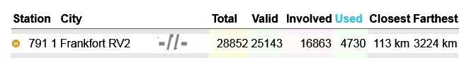
USED / TOTAL : Highly Variable per event / situations 4730 ÷ 28852 = 16%
USED / VALID : Also highly Variable 4730 ÷ 25143 = 19%
USED / INVOLVED : Also highly Variable 4730 ÷ 16863 = 28%
INVOLVED / VALID : Better Indication of Performance / quality 16863 ÷ 25143 = 67%
INVOLVED / TOTAL : BEST indication of overall Performance 16863 ÷ 28852 = 58%
VALID / TOTAL : INDICATION OF CONSISTENCY, settings, and environment 25143 ÷ 28852 = 87%
and, generally for most stations, a suggestion:
Closest >80km± (50m) Farthest <3200km± (2000m)
Notes:
A LOT of NOISE /JUNK signals can skew all the 'indicators'. Remember, those will be 'Sieved', affecting my station's DNA... If my "Total" is consistently higher than other regional stations, I may need to re-evaluate my 'optimization' settings and antenna placement.
"Automatic" Mode may not be the best operational mode. Generally a properly optimized / located station will perform better overall in Manual Mode. I did NOT use 'Automatics' to optimize my stations.. I did this in manual mode, over time. I operate in full Manual - no automatics.
System BLUE... I DON'T enable optional filters, unless I absolutely need them. The server 'delay' algorithms are still being optimized. I may see a decrease in performance, because of that, as well as other factors situationally related to 'decreasing' the channel bandwidth.
I made sure my Station Operator's page has the correct antenna configuration, types, size in the station data.
I operate with HP ON to enable as wide bandwidth as designed. Not optimum for some stations. HP OFF limits bandwidth to approx 60 KHz.
I see conditions where majority of VALIDS may be from E channel, rather than H channels... especially in daytime, depending on Ionosphere, and cell location. I don't under-estimate the E Probe assembly!
Part of "USELESS SIGNAL" mitigation: I accept interference modes, both "Burst" and "Normal".
Cheers!
Cutty Sark Sailor Stations 689, 791, 1439, Kentucky USA
Frankfort Weather